


Research Article - (2025) Volume 3, Issue 3
Triad: A Small-Footprint High Frequency Antenna System Design
Received Date: Feb 01, 2025 / Accepted Date: Mar 03, 2025 / Published Date: Mar 10, 2025
Copyright: ©2025 Marcus O. Durham, et al. This is an open-access article distributed under the terms of the Creative Commons Attribution License, which permits unrestricted use, distribution, and reproduction in any medium, provided the original author and source are credited.
Citation: Durham, M. O., Durham, P. R., Durham, R. A. (2025). Triad: A Small-Footprint High Frequency Antenna System Design. Eng OA, 3(3), 01-06.
Abstract
The objective is to develop high-frequency (HF) antenna systems that are small, unobtrusive, usable in limited space, indoor or portable, not exposed to lightning, easily configurable, requiring only simple tools, minimum install, without climbing, and inexpensive. Construction, tests, and measurements clearly illustrate an HF antenna system can be greatly reduced in size to a couple of meters.
Ten circuit design implementations condense HF antennas to a miniscule space, resulting in dramatically lessened environmental impact. A key consideration is changing every antenna element to a tunable inductor. Add inductor elements for wider bandwidth and multi-band. SWR, impedance, and frequency plots illustrate the fascinating performance.
Most contemporary antennas are variations of the balanced dipole used by Hertz in 1888 or the unbalanced monopole advocated by Marconi in 1895. Little has changed in high frequency antennas since those early two designs. This design is closely-coupled to the earth, more reminiscent of Tesla. Below 30 MHz, antennas are still largely long-wires with distributed electrical and magnetic properties. All antenna circuits have two electrical connections: 1) the radiator and 2) the electrical return, comprised of the monopole counterpoise or the dipole non-radiating side. More creativity options exist on the return side of the circuit than on the radiator. This article summarizes the NM0D Triad antenna system, which fits all the objectives.
Keywords
Triad Antenna, Alternative Antenna, High Frequency Indoor, Tesla, Not-Long-Wire, Small Footprint, Tunable Inductor
Introduction
High Frequency (HF) is the part of the electromagnetic spectrum between 100-meters and 10-meters (3 MHz – 30 MHz). This segment was part of the earliest development of long-distance telecommunications. The long-wavelengths create challenging antenna and circuitry design and installations. It contrast, it is these phenomena that make the spectrum unmatched for communicating point-to-point in the niches of harsh terrain such as hills, forests, and locations without infrastructure [1-4].
Our research antenna farm has a 132-ft long line for 160 & 80-meter as a dipole or end-fed. Other long wires are 40-, 20-, and 10-meter, with numerous end-fed and multi-band of various designs. Additional VHF and UHF antennas cover much of the communications spectrum. However, those systems cannot be installed in many locations, because of circumstances including legal, financial, and technological constraints.
Ten Design Considerations
Ten key circuit design implementations condense HF, as well as VHF, antennas to a miniscule triad, with three tunable elements. Some or all of these can be implemented, depending on space and environment requirements. Like all designs, these have trade-offs which impact performance, as illustrated.
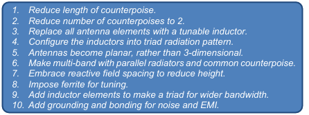
To some, these variations go against traditional dogma. Before construction, we developed models, then measured performance for validation. These design constraints provide a viable antenna where otherwise communications may not be possible.
Reduce Length of Counterpoise
A monopole with counterpoise drooped 45 degrees tunes quiet well with the counterpoise length cut from the normal λ/4 (quarter wave) to as short as λ/12. As counterpoise elements shorten, the radiator requires increased inductance, either by additional length or a coil. Moreover, for our small-footprint purposes, shortening the counterpoise by that amount greatly reduces the volume the antenna occupies.
Reduce Number of Counterpoises to 2
Reducing the number of counterpoise elements to just two gives another significant reduction in size.
The performance is within about 0.3 dB of larger systems, not even a blip on the S-meter [5].
Replace all Antenna Elements with a Tunable Inductor
The volumetric size shrinks from a nominal 40-meter length (λ/2) for 3.75 MHz to a span about 2-meters.
To compensate for mismatched (impedance) or untuned (frequency), add inductance (coils or length).
As one implementation, consider a 40-meter band antenna that fits in the space of a small triangle 1.4 m (4.5 ft) high and 102 cm (2.3 ft) wide. A 20-m system is even smaller as shown in Figure 1.
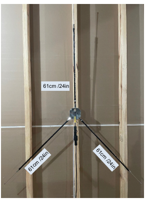
Figure 1: Triad 20-m Dimensions for Reduced Footprint
We have used a variety of tunable elements. One-type is a commercially available, high-frequency stick antenna for mobile use. The stick inductor consists of a hollow Fiberglas shaft, spiral wrapped with nominal 14-gauge wire, including a tightly wrapped loading coil near the center. The mechanical base uses a standard 3/8”-24 thread. The electrical top has a 3.175 mm (0.125 in) diameter adjustable length whip. Mobile base-loading coils with a whip work equally well.
The coil and whip combination has three significant capabilities: (1) adjust the inductance, (2) change the frequency, and (3) move the SWR. Performance improves by replacing the very high resistance stainless steel tunable whip with a copper, aluminum, or brass rod, where the environment permits.
The size for six through twenty-meter band antennas have a 61 cm (24 in) shaft inductor with the whip extending about 12 cm (5 in) when tuned. The forty and eighty-meter band devices are 91 cm (36 in) long with the eighty-meter whip extending about 79 cm (31 in) when tuned. [6] Tune the whip length for the frequency by observing an antenna analyzer.
A key point is the tunable inductor performs as a nominal quarter wave resonant element. Consequently, they are usable equally as a radiator or counterpoise return. The design uses three of the elements for most if not all antenna designs, forms, or designations.
Configure the Inductors into Triad Radiation Pattern
Hertz dipole and Marconi monopole antenna elements can be arranged in at least seven forms to change pattern and propagation. Many shapes, including inverted-vee, were evaluated, but provide little incremental benefit. Because of its unique coupling to earth, the triad can effectively replace these. A miniscule antenna for virtually any purpose is possible. As an example, a 40-meter system can hang on a wall or behind a curtain, rather than the environmental impact of covering a large land area at a high elevation.
One notice is important. Since the antenna is so small and low, the user may be tempted to place it near the operating station and people. Evaluate the health effects using normal radiation protocol.
Antennas Become Planar, Rather than 3-Dimensional
The numerous variations of antenna installations all have three things in common. The radiator requires a connection from the source and isolation from the mount. The return (counterpoise or non- radiating dipole) must allow for various orientation angles and requires bonding to the mount. The mount must affix to supporting structures. Although sounding almost trivial, those three criteria are the crux of an antenna system.
The long elements at high elevation create a massive three dimensional system. The triad vertical with two counterpoise is essential flat. We use a simple electrical trade size 4-in steel octagon box for the counterpoise mount and an antenna adapter to f ix the radiator.
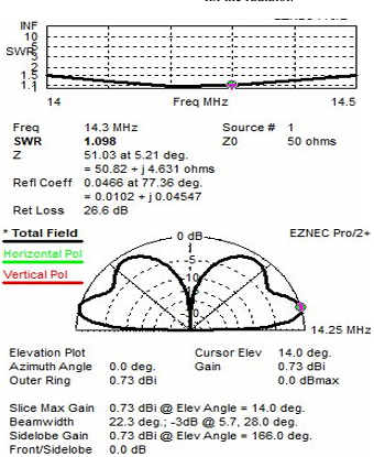
Figure 2: 20-m Triad Model
Make Multi-Band with Parallel Radiators and Common Counterpoise
The triad configuration, shown in Figure 1, is a vertical monopole with two drooping counterpoises. For 20-meters, each of the elements is 61cm (24 in) long. The whip extensions vary as frequency is tuned, but are about 12 cm (5 in). The entire displacement is approximately 127 cm (50 in) high by 102 cm (40 in). The depth is only 3.8 cm (1.5 in). Because the tunable inductors are the same length, a 15-, 10-, or 6-meter antenna system is similar in size to the 20-meter system.
The counterpoise can be rated for the same band or for a higher band up to one-third the wavelength.
Consistent with the shortening section, the one-third derives from a reduced length λ/12 counterpoise compared to the nominal λ/4 element.
Interestingly, that property allows a multi-band antenna by placing radiators in parallel, but using the same common counterpoise. A 20, 17, 15, 12, 11, or 10-meter radiator can share a 10-meter counterpoise. Because of mutual coupling, tuning each band can take a little more effort.
The miniscule width, height, and depth make the antenna very usable. These configurations are flexible, allowing high frequency, long wavelength antennas to fit in a small space, to be portable, or to operate fixed-mobile. Figure 2 is an Eznec model of a conventional triad [7].
Embrace Reactive Field Spacing (< λ/6) to Reduce Height
For conventional long-wire antennas, the feed-point would be λ/6 above the earth surface to get outside the reactive field interference. Seldom is that height possible. The feed-point for the eighty-meter band is 13.4 m (44 ft) high. Rather than struggle for more height, our approach uses the reactive field to reduce height, like the meander design in cellphones and floating wire design for submarines [8].
Since the counterpoise (return) is tunable, it can compensate for proximity of the ‘ground / earth’. Tests show the lowest elevation is with the counterpoise physically touching the ground. Up to attic height of 5- meters (15-feet) is still effective [9-11].
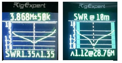
Figure 3: Measured Performance for 80-m and 10-m
Impose Ferrite for Tuning
Within 20 cm (8 in) below the SO-239 connection to the radiator, snap on 4 to 7 ferrite beads of Type 31 mix. Lower frequencies require more beads. Without ferrite, the coax shield becomes an undesirable, untunable part of the counterpoise, whose reactance changes by capacitive coupling. The ceramic cores provide other important contributions. Notably, the ferrite reduces the effect of surrounding electro-magnetic noise and common-mode currents.
Add Inductor Elements to Widen Bandwidth Tests employed an Icom IC-7300 transceivers with power limited to 100-Watts and a Rig-Expert Stick Pro. No measurements or configurations required an external antenna tuner, since the antennas are resonant.
These are raw values from just the tunable inductor elements and coax. The charts in the figures are representative and do not illustrate all tests. Further tweaks for fine tuning will improve results. All measurements have the feed-point elevated to 4.5 m (15 ft) above earth, inside a building.
A 10-meter band triad vertical with 6-meter band droop counterpoise has SWR of 1.12 :1, which is very impressive. An antenna analyzer yielded the graph in Figure 3 right.
Similarly, an 80-meter band (3.8 MHz) has an SWR of 1.35 as identified in the graph of Figure 3 left.
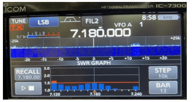
Figure 4: Measured Performance for 40-m added Bandwidth
One way to increase bandwidth is by mounting two radiator elements in parallel on a nominal 7.5 cm (3 in) metal bar. Tune each inductor to a slightly different frequency either side of the desired center. The performance of a 40-meter band triad with two radiators is shown by the chart in Figure 4. The blue-bar SWR is what the radio transmitter detects. Note the two valleys or dips, one for each element.
Another effective method is to use the radiator and the first return (counterpoise) tuned to one side of the band, often the lower frequency. Then the other counterpoise inductor gets tuned to the other side of the bandwidth. The combination creates a much wider band with acceptable SWR. The response, as seen by the radio, of a 10-meter triad was virtually flat until near the edge. Figure 5 illustrates very low blue peaks on SWR.
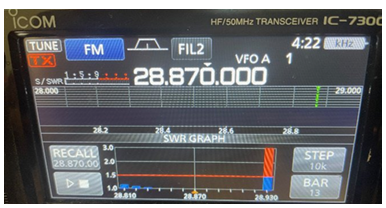
Figure 5: Tuned 10-meter is flat
Add Grounding and Bonding for Noise and EMI
Noise is a limiting factor. An S5 signal with S5 noise is non-pro- ductive. With all antennas, surrounding electromagnetic interfer- ence (EMI), location of radiator, coaxial routing, connections, number of ferrite beads, and grounding are noise control matters. A lightning protection or similar shunt device with adequate ground, mounted below the ferrite, is often beneficial to reroute some un- wanted noise, even on indoor antennas.
Since the return side (counterpoise) is a resonant inductor, adding a ground conductor at the mount above the chokes will shift the frequency response.
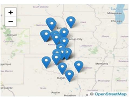
Figure 6: 40-m net Contacts (MW photo)
Results
Although we designed, engineered, and developed the antenna, a team of seven Extra/General class amateur radio operators, built, tested, gave feedback, and use the antennas as part of the research and for their routine HF communications. Captain Mike Watson (USN), KJ5DRI, has done extensive experimenting with hundreds of contacts using the Triad antennas from his fishbowl location with surrounding hills. His Triad farm consists of dual band 6+10, 15+20, and 40+80 witha tee [12].
On 80-m and 40-m, conversations are routine with NVIS (near vertical incident skywave) net stations within 5-miles and out to 400 miles. Besides 20-m, other contacts include 15-m to New Hampshire. 10-m contacts include Grand Cayman, Virginia, and California. These are a few examples to show the system works exceptionally across the spectrum. Clearly the Triad is not conventional NVIS radiation, but communicates well with those type stations, through its effective earth-bound energy transfer.
Conclusion
Great innovation involves numerous incremental steps. We listed ten significant design implementations to reduce the physical space of HF antennas from hectares (acres) to centimeters (inches). No one change would accomplish the goal. As expected, the small-footprint antenna has some trade-offs. Nevertheless, it allows operation where conventional antennas are not viable. This is a first-generation design approach. Additional development of inductors should improve its operations.
The NM0D Triad design opens HF communications to many more locations and applications. The system is well-fitted for emergency, search-and-rescue, limited-space, and military communications. For amateur applications, the system is apartment usable, HOA (home owners association) friendly, with minimal lightning exposure.
Biographical Sketch
Marcus O. Durham, PhD, Th.D. is a failure analyst emeritus, Professor Emeritus, and amateur extra NM0D.
Pruitt, his grandson, is an operations engineer.
Dr. Robert, his son, is a failure analyst and research scientist who runs the family business. All are electrical engineers
References
1. Durham, M., Durham, P. R., & Durham, R. A. (2024). Marconi Redux: Small-Footprint High-Frequency Antenna System Design. Authorea Preprints.
2. A. Williams, “Why High Frequency Radio Remains Crucial for Military Communications,” Army Technology.
3. T. Carter, “NVIS Solves a 30-Year Problem,” QST. Newington, CT: ARRL pp. 61-63, July 2023.
4. “HF Military Communications”, The Radio Reference Wiki.
5. Moxon, L. A. (2011). HF Antennas for all Locations. Radio Society of Great Britain.
6. GigaParts Technology, “Shark Mono Band Verticals”.
7. R. Lewallen, EZNEC Pro/2+ v.7.0. retrieved 29 Nov 2023.
8. J. Merrill, “Floating Wire Antennas Communicating with a Submerged Submarine,” Naval Submarine League.
9. M. O. Durham, Unified Field Theory in One Energy Equation. ISBN:978-1467950701; Bixby, OK: Theway Labs, 2012.
10. Durham, M. O., Durham, R. A., & Durham, K. D. (2002, September). Applications engineering approach to Maxwell and other mathematically intense problems. In Record of Conference Papers. Industry Applications Society. Forty Ninth Annual Conference. 2002 Petroleum and Chemical Industry Technical Conference (pp. 31-38). IEEE.
11. Durham, M. O., & Durham, R. A. (2013). Does a unified energy equation contain the higgs field?. IEEE Access, 1, 505 508.
12. M.O. Durham, R Durham, Ham (Amateur) Radio Evergreen Book: Establish reliable, lowest technical common denominator communications, locally & regionally, in a HOA, Theway Labs, ISBN: 9798306770734, Bixby OK: Theway Labs, 2025.