
Advances in Machine Learning & Artificial Intelligence(AMLAI)
ISSN: 2769-545X | DOI: 10.33140/AMLAI

Review Article - (2024) Volume 5, Issue 4
Millimeter wave MPA using Metamaterial-substrate Antenna array for Gain Enhancement
Received Date: Jan 12, 2024 / Accepted Date: Aug 18, 2024 / Published Date: Nov 11, 2024
Copyright: ©2024 Rishitha Komatineni, et al. This is an open-access article distributed under the terms of the Creative Commons Attribution License, which permits unrestricted use, distribution, and reproduction in any medium, provided the original author and source are credited.
Citation: Komatineni, R., Dasari, V., Hruday, C. S., Vutukuru, V. S., Mishra, P., et. al. (2024). Millimeter wave MPA using metamaterial-substrate antenna array for gain enhancement. Adv Mach Lear Art Inte, 5(4), 01-06.
Abstract
This paper presents a Millimeter wave Microstrip Patch antenna(MPA) with a metaplate which consists of Split Ring resonators(SRR) design. The gain and bandwidth of MPA are improved by using 4×3 array unit cells printed on both the sides of the metaplate. Simulation results show that the Gain of the antenna was increased by 4.82 dBi and 4.53 dBi, bandwidth was increased by 2.25% and 6.21% in CST and HFSS softwares respectively using the Metaplate along with the MPA. The center frequency of the proposed antenna is 28.5 GHz. Thus the proposed antenna has a very small size of 18×22 mm2 and is suitable for Millimeter wave applications.
Keywords
Microstrip Patch Antenna(MPA), Split Ring Resonator(SRR), Metamaterials, Superstrate ,Millimeter Waves, CST, HFSS
Introduction
In the current scenario where the internet is the medium that helps millions to continue their work online, billions to continue their education and a lot of people to connect with each other, Fourth generation(4G) services helped us a lot. But with increasing requirement in the field of science and technology Fifth generation(5G) can perform the work more easily when compared to other generations. There are two sets of frequency bands for 5G networks. From 450 MHz to 6 GHz is the sub-6 GHz region and the Millimeter wave(mm wave) spectrum ranges between 30 and 300 GHz. For 4G and prior generations, we have used radio waves for transmission which have a low bandwidth and are widely utilized by mobile operators, resulting in slower service and more failed connections [1]. So, having the future in mind, we’ll need a medium that can handle a lot of data. The millimeter wave area, which has never been used before, is a great answer for this. It eliminates the spectrum crowding problem and permits communication at very high data speeds thanks to its extremely wide bandwidth. Highdirectivity antennas can be constructed with a tiny footprint due to the short wavelength. Antennas for higher frequency (mm wave) applications (such as 5G) must be extremely stable, with high radiation efficiency, high gain, and great temperature stability [2].In the last decade, the microstrip patch antenna has become one of the most popular and commonly used antenna types. The introduction of low-cost microstrip antenna production processes has improved the popularity of microstrip antennas. Microstrip patch antennas are low-cost, low-profile, lightweight, and relatively easy to make [3]. Although the Conventional Microstrip Patch Antenna has a lot of good features, its narrow bandwidth and low gain makes it unsuitable for Millimeter wave applications[2].In order to solve this problem there are a lot of techniques that are being used by the researchers such as increasing the thickness of the substrate, incorporating antenna arrays and Metamaterials in the design. Array antennas can boost gain and efficiency, but they have a huge size and complex structure that makes them difficult to use. In recent times use of Meta- materials have become a promising technique to increase the gain and also to reduce the size of the antenna. Metamaterials are basically those materials which possess electromagnetic properties that are not found in nature, such as a negative index of refraction. Electromagnetic waves are refracted in the opposite direction due to the negative index of refraction, causing focus which increases the gain, directivity and also the bandwidth of the antenna [2,4-6].In Reference 9, Millimeter wave antenna array is presented. In Reference 11, a MIMO antenna with metamaterial substrate for WLAN applications is presented. In Reference 14, multiband metamaterial based antenna is presented. But all these antennas have low gain at 28.5GHz.In this paper, the performance of Microstrip Patch antenna is improved using a metapelite which have Split ring resonators printed on both the sides for better gain. The center frequency is set to be 28.5 GHz. After successful simulation of the design in the CST software we verified the results in HFSS software and they are compared. The antenna with metapelite showed improvement in terms of gain and bandwidth when compared to conventional microstrip patch antenna.
Microstrip Patch Antenna Design
The Design of the Microstrip Patch Antenna is shown in Figure 1. The dielectric substrate must be broad and have a low dielectric constant to achieve superior antenna performance, greater antenna efficiency, wider bandwidth, and significantly better radiation [2]. The substrate used for the Microstrip patch antenna is the Taconic TLY-5(εr = 2.2,tangent loss = 0.009).The low dissipation, stable and uniform dielectric constant, and reduced moisture absorption factor facilitate effective deployment of millimeter wave antennas. The Dimensions of the patch antenna were calculated using the formulas [7]:
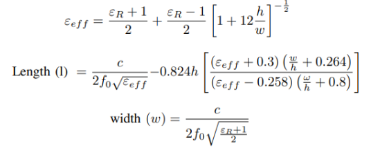
These values were then optimized to get the best performance at the center frequency of 28.5 GHz. Microstrip Patch antenna is engraved on the Substrate of dimensions S1 = 22mm, Sw= 18mm and thickness T = 0.8mm.The ground plane and patch are of copper material. The dimensions of the patch are Lp = 3mm, Wp = 4.5mm with the feedline dimensions of F1 = 1.66mm, F2 = 6.9mm, W1 = 0.9mm, W2 = 2.31mm.The microstrip patch antenna is excited using a variety of feeding mechanisms. Microstrip line feed is a frequent and easy method of connecting the microstrip antenna in the middle of one of its edges. The impedance of Microstrip patch antenna is matched using a quarter wavelength (λ/4) transformer and it is fed by a 50-â?¦ microstrip line. Figure 2 and 3 shows the reflection coefficient and gain of the antenna respectively. The bandwidth of the MPA is 7.89% ranging from 27.51 GHz to 29.76 GHz and the peak gain was observed as 9.52dBi.
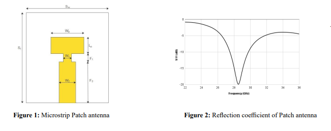
Figure 3: Gains of the Patch Antenna
Metamaterial Unit Cell Design
The figure 4,5 shows the front and side views of the unit cell respectively. The structure consists of Split ring resonators (SRR). In a single cell SRR, there are two enclosed loops with splits at opposite ends. The loops are of copper material, concentric in nature and are separated by a short gap. The huge capacitance values produced by the narrow gaps between the rings lower the resonant frequency. As a result, the structure’s dimensions are modest in comparison to the resonant wavelength and therefore, there are Low radiative losses and good quality factors. The unit cell is placed on a substrate of length sL = 3.5mm, width sW = 3.5mm and thickness T1= 1mm.The dimensions of the SRR are R1 = 1.3mm, R2 = 0.9mm, d = 0.2mm, g = 0.1mm respectively. Electric field propagation along the Y-axis and magnetic field propagation in the Z-direction are the unit cell’s boundary conditions. A unit cell array is placed on the top of the substrate and then on the backside of the substrate they are rotated by 180 degrees. From figure 6 we can see that the -10 dB bandwidth is from 26.973 GHz to 27.856 GHz.
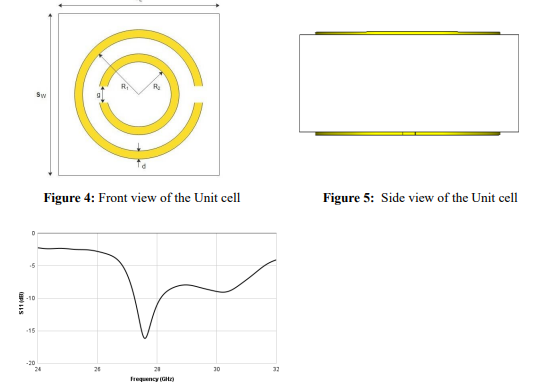
Figure 6: Reflection coefficient of unit cell
Proposed Antenna Design
In this paper we are using a Metamaterial plate consisting of 4*3 unit cells to enhance the gain and bandwidth of the Microstrip patch antenna. Figure 7 shows the Top view of the Metaplate, Figure 8 shows the complete structure of the proposed antenna. A 4×3 unit cell array is placed on the top of the metaplate and then on the backside of the plate they are rotated by 180 degrees. The distance between the MPA and the metaplate also plays a crucial role in improving the gain and the bandwidth of the antenna. After studying the gain and bandwidth for various values of this distance it is chosen to be 16mm for better results. Then the spacing between the rows and columns of unit cells has been studied by fixing the superstrate distance at 16mm and the spacing is chosen to be 0.7mm in both directions for best performance.

Figure 7: Top view of the Metaplate Figure 8: Proposed Design
Results
Figure 9 and 10 shows the reflection coefficient and gain graphs for different configurations of unit cells and results are tabulated in table 1.
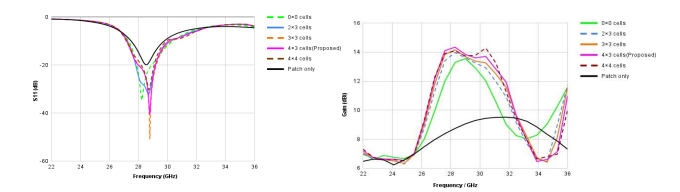
Figure 9: Reflection coefficient of various configurations of unit cells Figure 10: Gain of various configurations of unit cells
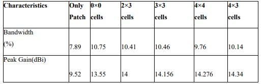
Table 1: Performance comparison of different numbers of unit cells
As observed from Table 1 the ideal number of unit cells to obtain the maximum performance of antenna is 4×3. Results are then verified in the HFSS (High Frequency Structure Simulator) software. Figure 11 and 12 shows the reflection coefficient and gain of the MPA with metaplate respectively in both CST and HFSS softwares and figure 13 shows the radiation pattern of the proposed antenna in CST. It is seen that the bandwidth of the MPA with metaplate has been increased by 2.25% and 6.21%, gain has been increased by 4.82 dBi and 4.53 dBi in CST and HFSS softwares respectively when compared to conventional Microstrip patch antenna. Therefore, it is verified that metaplate produces a focus because of its properties which in turn has increased the directivity, eventually increasing the gain and bandwidth of the antenna.
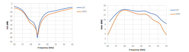
Figure 11: Reflection coefficient of the Antenna in CST and HFSS Figure 12: Gain of the Antenna in CST and HFSS
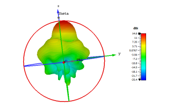
Figure 13: Radiation Pattern of the Antenna at 28.5 GHz
Conclusion
Millimeter wave Microstrip Patch Antenna with a metaplate consisting of Split Ring Resonator(SRR) is proposed and simulated in two different softwares-CST and HFSS. The performance of the microstrip patch antenna has improved significantly by using a metaplate. The antenna shows a peak gain of 14.34 dBi and 14.05 dBi, bandwidth of 10.14% and 14.1% in CST and HFSS software’s respectively. Since HFSS uses Finite Element Method (FEM) and CST uses Finite Integration in Technique (FIT),there is a slight difference in the results. Considering the high gain, high bandwidth and small size of the antenna it is suitable for 5G millimeter wave applications [8-13].
References
1. Osseiran. (2014). Mobile and Wireless Communications system for 2020 and beyond (5G). workshop on Research views on IMT beyond 2020.
2. Arora, C., Pattnaik, S. S., & Baral, R. N. (2018). Metamaterial inspired DNG superstrate for performance improvement of microstrip patch antenna array. International Journal of Microwave and Wireless Technologies, 10(3), 318-327.
3. Liu, Z., Wang, P., & Zeng, Z. (2013). Enhancement of the gain for microstrip antennas using negative permeability metamaterial on low temperature co-fired ceramic (LTCC) substrate. IEEE antennas and wireless propagation letters, 12, 429-432.
4. Mookiah, P., & Dandekar, K. R. (2009). Metamaterialsubstrate antenna array for MIMO communication system. IEEE Transactions on Antennas and Propagation, 57(10), 3283-3292.
5. Lou, R. K. M., Aribi, T., & Ghobadi, C. (2010, December). Improvement of characteristics of microstrip antenna using of metamaterial superstrate. In International conference on communication engineering (pp. 126-129).
6. Aziz, C. H., & Al-Hindawi, A. M. (2016). Electromagnetic effect of rectangular spiral metamaterial on microstrip patch antenna performance. Journal of Modeling and Simulation of Antennas and Propagation, 2(1), 13-21.
7. Patel, D. N., Vayada, M. G., & Nayak, V. H. (2014). Improvement in Characteristics of Micro strip Antenna with the Help of Different Meta material Structures. International Journal for Innovative Research in Science Technology, 1(6).
8. Park, S. J., Shin, D. H., & Park, S. O. (2015). Low side-lobe substrate-integrated-waveguide antenna array using broadband unequal feeding network for millimeter-wave handset device. IEEE Transactions on Antennas and Propagation, 64(3), 923- 932.
9. Ta, S. X., & Park, I. (2016). Cavityâ?backed angledâ?dipole antennas for millimeterâ?wave wireless applications. International Journal of Antennas and Propagation, 2016(1), 5083807.
10. Akbari, M., Ghalyon, H. A., Farahani, M., Sebak, A. R., & Denidni, T. A. (2017). Spatially decoupling of CP antennas based on FSS for 30-GHz MIMO systems. IEEE Access, 5, 6527-6537.
11. Mark, R., Rajak, N., Mandal, K., & Das, S. (2019). Isolation and gain enhancement using metamaterial based superstrate for MIMO applications. Radioengineering, 28(4), 689-695.
12. Hassan, T., Khan, M. U., Attia, H., & Sharawi, M. S. (2018). An FSS based correlation reduction technique for MIMO antennas. IEEE Transactions on Antennas and Propagation, 66(9), 4900-4905.
13. Liu, F., Guo, J., Zhao, L., Shen, X., & Yin, Y. (2018). A metasurface decoupling method for two linear polarized antenna array in sub-6 GHz base station applications. IEEE Access, 7, 2759-2768.
14. Khan, J., Sehrai, D. A., & Ahmad, S. (2018). Design and performance comparison of metamaterial based antenna for 4G/5G mobile devices. International Journal of Electronics and Communication Engineering, 12(6), 382-387.